In piping design and fabrication, pipe spools are prefabricated sections of piping typically including pipe segments, fittings, flanges, valves, or other inline components that are manufactured in the workshop and later assembled on-site.
Thinking in spools offers several advantages:
- Efficiency: Prefabrication reduces time and labor on the construction site.
- Accuracy: Clear definitions of each spool minimize errors during assembly.
- Quality Control: Work in a controlled environment ensures better welding and inspection.
- Logistics: Spools can be tracked, transported, and installed systematically.
Instead of handling an entire piping system as one large and complex entity, spool-based design breaks it down into manageable, well-defined building blocks.
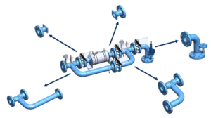
Figure 1 – Pipe Spools
The 3D model as the single source of truth
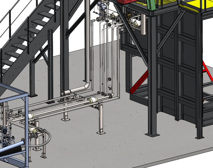
In Smap3D, the 3D model is the driver for all downstream documentation. Every isometric drawing is automatically generated from the piping 3D assembly. This means:
- The model must be built with precision.
- All properties and component information need to be correctly defined.
- Tag numbers (for valves, instruments, inline components) can either be assigned directly in the 3D CAD model or – if all three Smap3D modules are used – transferred seamlessly from the P&ID.
This ensures that every step, from design to fabrication drawing, is based on consistent and reliable data.
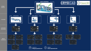
Figure 2 – 3D model is the driver for all downstream documentation
Spool analyzer: bringing spool information back into the 3D environment
Another powerful feature within Smap3D is the Spool Analyzer. While spool drawings are created in the isometric stage, the Spool Analyzer takes this information a step further by sending the spool definitions back into the 3D CAD environment.
In practice, this means that the software recognizes where a pipeline has been divided into spools and reflects that structure directly inside the 3D assembly. For example, in SOLIDWORKS, each spool can automatically be organized into its own subfolder within the assembly tree.
For the 3D designer, this offers several benefits:
- Clear visibility of how the pipeline is broken down into spools.
- Easier management of assemblies with many prefabricated sections.
- Better coordination between design, isometrics, and fabrication teams.
In addition, all installation parts are automatically placed into a dedicated ERECTION folder. This ensures that every part of the pipeline is accounted for, whether it is prefabricated as part of a spool or installed separately during construction.
This tight integration closes the loop between design and documentation, ensuring that spool-based organization is consistent and transparent across all stages of the project.
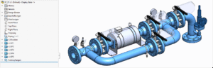
Figure 3 – Spool Analyzer – Spool Folder Structure in Solidworks
Isometric drawings
Smap3D generates isometrics for each pipeline sub-assembly. From these, you can produce:
- General Isometric Drawings: Show the full pipeline, dimensions, and BOM including installation and fabrication parts for overview and reference.
- Spool Drawings: Break down the pipeline into smaller, prefabricated units. These drawings contain only the relevant section of piping, with weld points, dimensions, and unique spool IDs for fabrication.
This distinction is crucial while overview isometrics are useful for planning and coordination, spool drawings are what the workshop and site teams need for actual fabrication and assembly.
Attribute mapping and automation
Behind the scenes, Smap3D uses PCF files to transfer all 3D attributes into the Isogen module. Properties such as component tags, line numbers, material specs, and spool IDs are mapped and converted into automated isometric outputs.
You can think of this process as a kind of translation: all the information stored in the 3D CAD model is read out, interpreted, and then passed on to Isogen. Only if these mappings are defined correctly can the data be transferred without errors – ensuring that the resulting isometric drawings contain the right dimensions, component IDs, and spool references.
The result: standard-compliant isometric drawings that require no manual drafting effort.
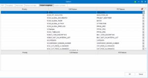
Figure 4 – Isometric Feature Mapping
Spool ID generation and assignment
One of the challenges in spool-based fabrication is keeping track of dozens of spools within a single pipeline. Especially when multiple spools look similar, it can be difficult for designers and workshop staff to correctly assign the right drawings to the right sections.
Smap3D addresses this by automatically generating a unique Spool ID for every spool. This ID is not only displayed in the overview isometric drawing, but is also included in the file name of each spool drawing as well as directly inside the spool drawing itself.
This clear identification eliminates confusion and drastically reduces the need for manual rework. Having the spool ID consistently embedded ensures that every spool can be quickly assigned, tracked, and handed over to fabrication without errors.
To make spool identification even clearer, Smap3D allows the Spool ID to be embedded directly in the file name of each drawing. This is configured in the Isometrics Settings under Templates → Drawing Style, where the attribute $SPOOL-NAME$ can be added.
If additional information should appear in the file name – for example, a pipeline number or a project reference – this can be achieved through intelligent mapping of custom properties from the 3D CAD model (e.g., SolidWorks) into corresponding PCF attributes.
In the example shown, the file name is structured as follows:
- Skid reference (mapped to ATTRIBUTE9)
- Static field “10” (used in this project to indicate an isometric drawing)
- Pipeline number (mapped to ATTRIBUTE1)
- Spool ID
This structure makes it immediately clear which project, document type, pipeline, and spool the drawing belongs to ensuring transparency and traceability.
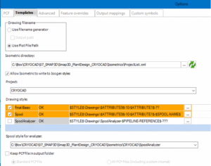
Figure 5 – Template settings isometric
Customization and consistency
Smap3D allows you to fully customize the appearance of spool drawings:
- Your own title blocks and borders.
- Company logo and project information.
- Templates aligned to your corporate drawing standards.
Most importantly, these settings are applied consistently across the organization. No matter which engineer or department creates an isometric, the output follows the same standard ensuring uniform documentation for fabrication, quality control, and client delivery.
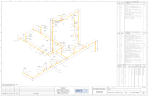
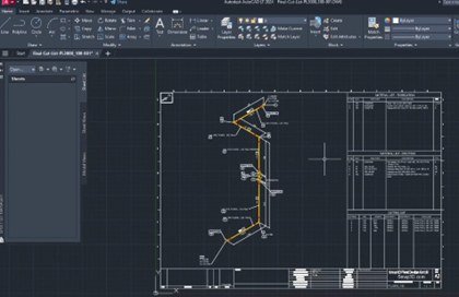
Figure 6 – Isometric Drawing Created with Smap3D
Save time, reduce errors
Traditional manual drafting of piping drawings can take an entire workday up to 8 hours for a single overview drawing (Ref: Figure 6). Even with an experienced designer, this process always carries the risk of errors: missing dimensions, forgotten notes, or inconsistencies between drawings. Such mistakes don’t just cost time; they can lead to delays and rework once the project moves into fabrication.
With Smap3D’s automated drawing generation, the same overview drawing (Ref: Figure 6) can be created in as little as 5 minutes. All dimensions, annotations, and component details are generated directly from the 3D model, ensuring accuracy and consistency across the entire documentation package. This not only speeds up project delivery but also gives engineers more time to focus on design quality and problem-solving, rather than repetitive manual drafting.
Conclusion
By thinking in spools and leveraging the automation capabilities of Smap3D, companies can move from complex piping models to fabrication-ready documentation with speed, accuracy, and consistency.
From P&ID to 3D piping to isometrics, every step is data-driven and automated – minimizing errors, standardizing workflows, and ensuring that every spool is clearly defined, traceable, and ready for production.
For engineering teams aiming to improve piping efficiency, spool-based design with Smap3D is not just a tool it’s a methodology that transforms the way projects are executed.
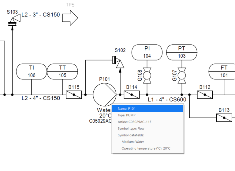
Figure 7 – Smap3D P&ID, Piping and Isometrics
Need support with isometrics or spools?
If you have questions about spool-based design, automated isometric generation, or how to best implement these workflows in Smap3D Plant Design, feel free to get in touch with us. At CryoCAD, we provide consulting, training, and hands-on design support to help engineering teams get the most out of their piping projects from setting up spool workflows to ensuring smooth and accurate isometric documentation.
Book a Smap3D demo with CryoCAD!