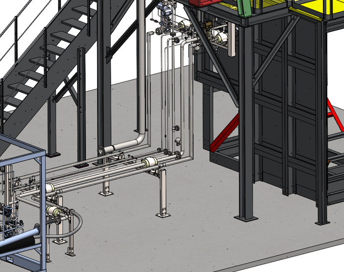
Process Flow Diagrams and Piping and Instrumentation Diagrams are among the most important documents in plant engineering. They define how a process works, how equipment is connected, which components are required, and how technical information is structured throughout a project.
For many companies, however, P&IDs are still created as largely graphical documents. Symbols are placed manually, lines are trimmed by hand, lists are maintained separately, and component information is often distributed across several systems.
Smap3D P&ID takes a different approach. It combines intelligent diagrams, structured component data, automated documentation, and optional integration with 3D plant design.
This article provides an overview of selected features that can help engineering teams create P&IDs more efficiently and maintain consistent data throughout the project.
INTELLIGENT SYMBOLS AND COMPONENTS
Smap3D P&ID includes extensive symbol libraries for equipment, valves, instruments, pumps, vessels, and many other component types.
Symbols can be selected from the library and placed directly on the drawing. When a symbol is positioned on a pipeline, it automatically aligns with the line and splits it at the correct location.
For users who are accustomed to creating P&IDs manually in AutoCAD, this is often one of the first noticeable improvements. No manual trimming is required.
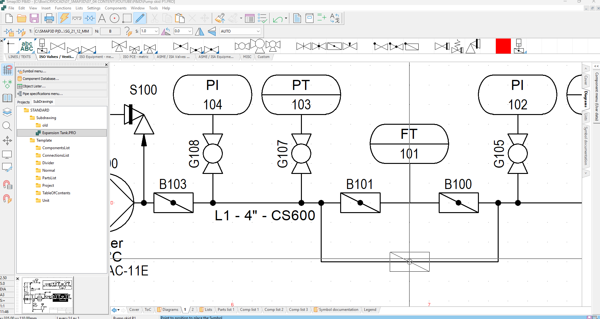
Figure 1 – Placing a Symbol on a Pipeline
At this stage, the symbol can initially remain generic. This is useful during the early design phase, when the required component type is already known but the exact manufacturer or article has not yet been selected.
For example, the process engineer may know that a butterfly valve or a pump is required without knowing the final product.
Once the specific component has been selected, the symbol can be connected to an entry in the component database.
When the exact article is already known, the component can also be selected directly from the database and dragged into the P&ID.
COMPONENT DATA AND PROJECT-SPECIFIC INFORMATION
A major advantage of intelligent P&ID software is the ability to distinguish between product data and project-specific process information.
The same physical pump, for example, may be used in several projects. The manufacturer, article number, dimensions, and technical product data may remain unchanged.
The operating conditions, however, can be different.
In one project, the pump may handle water at 20 degrees Celsius. In another project, the same pump may handle a different medium at 60 degrees Celsius.
Smap3D P&ID allows these different types of information to be managed separately within the component data structure.
This makes it possible to reuse standardized article data while still assigning the correct operating conditions for each individual application.
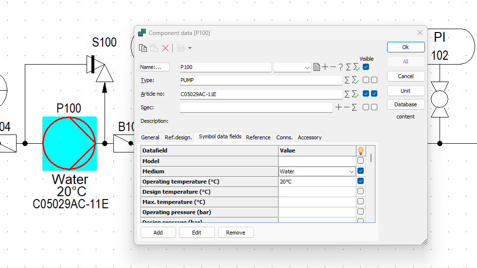
Figure 2 – Component Data Card
COMPONENT DATABASE AND ERP INTEGRATION
Smap3D P&ID can work with a central component database based on Microsoft Access or SQL.
The database can contain information such as:
- Internal article numbers
- Manufacturer data
- Product descriptions
- Technical properties
- Material information
- Dimensions
- Company-specific fields
Depending on the company’s IT environment and implementation concept, this data can also be connected or synchronized with an ERP system.
The goal is to ensure that engineering, purchasing, production, and other departments work with consistent article and product information.
Instead of entering the same data several times in different systems, the component information can be managed centrally and reused within the P&ID project.
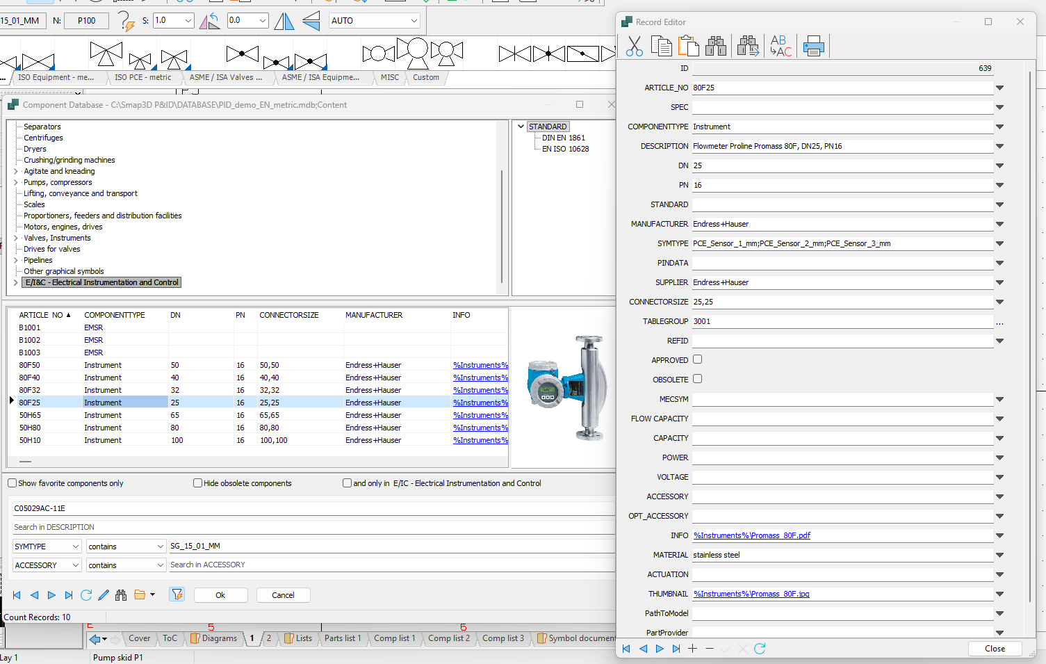
Figure 3 – Component Database
AUTOMATIC LIST GENERATION
Because the components contain structured information, Smap3D P&ID can automatically generate project lists.
These may include:
- Component lists
- Valve lists
- Instrument lists
- Equipment lists
- Pipeline lists
- Bills of materials
The content, filters, sorting rules, and layout of the lists can be adapted to company or project requirements.
For example, a complete component list can be sorted by tag number, while separate lists can be created for valves, instruments, or other specific component categories.
The major advantage is that the lists are generated directly from the P&ID project.
When component information changes, the lists can be updated accordingly. There is no need to maintain a separate manual spreadsheet alongside the drawing.
The generated data can also be exported to Excel for further processing or distribution.
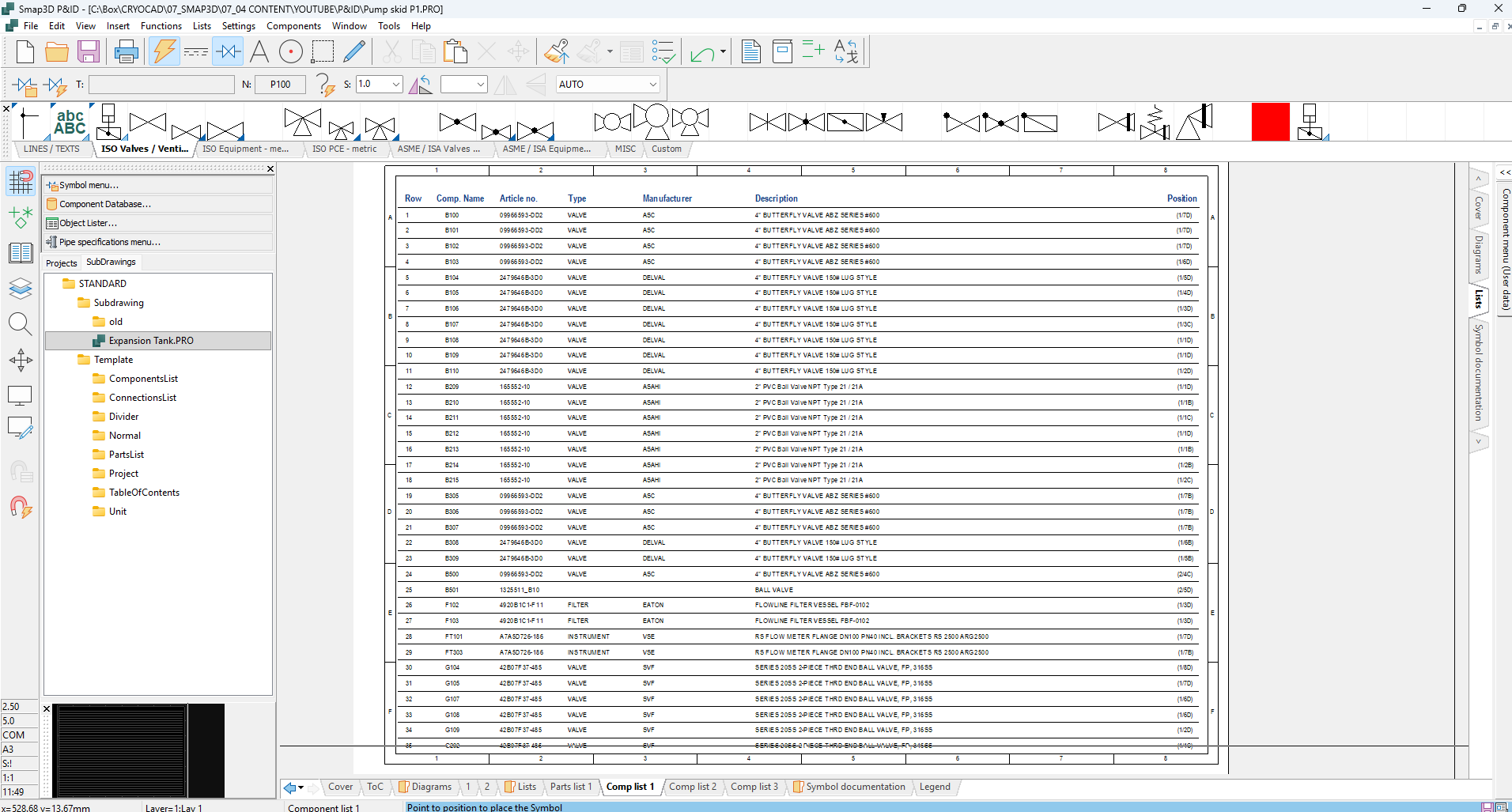
Figure 4 – Automatically Generated Component List
SMART PDF EXPORT
PDF export may sound like a standard feature, but Smap3D P&ID adds useful intelligence to the exported document.
Component and pipeline information can be embedded directly in the PDF file. Depending on the export configuration, users can click on a component or pipeline and view the associated data.
The displayed information is customizable. Companies can decide which properties should be included and whether additional data should be visible at all.
Transition arrows between drawing sheets can also remain interactive. Clicking an arrow takes the user directly to the corresponding sheet.
Components listed in project tables can also be linked to their location in the P&ID. This makes it easier to navigate large projects and quickly find specific equipment, valves, or instruments.
The recipient does not need Smap3D to use these functions. A standard PDF viewer is sufficient.
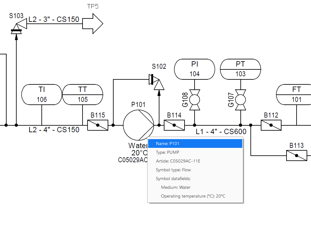
Figure 5 – Interactive Component Data Inside the PDF
REUSABLE SUBDRAWINGS
Many P&ID projects contain arrangements that are used repeatedly.
An expansion tank, for example, may normally include additional instruments, vent valves, drain valves, and other components.
Instead of rebuilding this arrangement for every new project, it can be stored as a subdrawing.
The complete arrangement can then be inserted into another project by drag and drop.
The individual components remain intelligent objects and continue to appear separately in the project lists.
Tag numbers can also be updated automatically during insertion, helping to prevent duplicate tags.
Subdrawings are therefore particularly useful for:
- Standard equipment arrangements
- Typical valve assemblies
- Frequently used process modules
- Customer-specific standard solutions
- Repeating skid sections
They reduce repetitive work while helping companies apply consistent design standards across multiple projects.
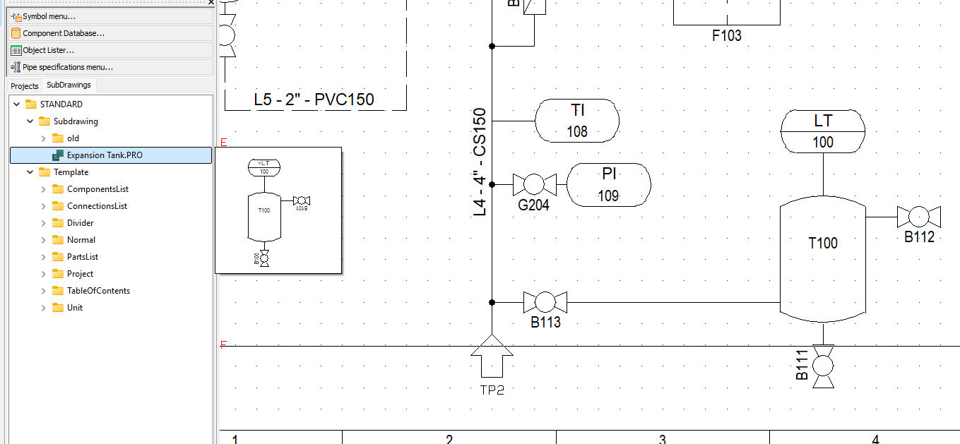
Figure 6 – Subdrawing Library
CONSISTENT TAGGING
Tagging is essential in every P&ID. It allows components to be identified, referenced, documented, and located throughout the project.
Smap3D P&ID includes several mechanisms that help users avoid duplicate tags and maintain a consistent tagging structure.
When a component is placed, one of the first properties assigned is its tag. In Smap3D P&ID, this property is commonly referred to as the component name.
A predefined prefix can be embedded in the symbol so that different component types automatically begin with the correct letters.
The sequential number can then be:
- Entered manually
- Counted up automatically
- Assigned using the next available number
- Checked against existing tags
Tags can also be updated automatically when components are copied or when subdrawings are inserted.
This reduces the risk of duplicate identification numbers and supports a consistent project-wide tagging standard.
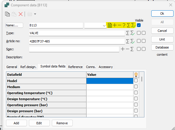
Figure 7 – Tag Assignment Options
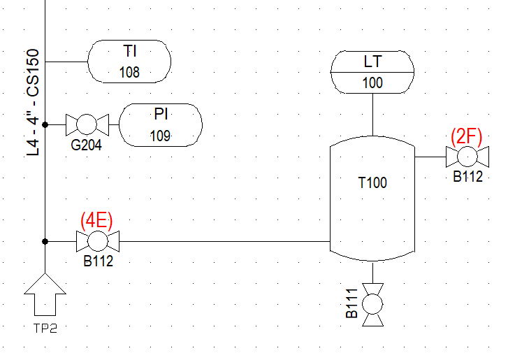
Figure 8 – Duplicate Tagging Warning
Tagging can be extended through the use of location aspects.
A location aspect identifies the physical or functional area in which a component belongs. This could be:
- A room
- A modular skid
- A plant section
- A production area
- A process unit
- A functional system
When the project is configured accordingly, the tag can change depending on where the component is placed within the P&ID.
This helps companies create a structured identification system that reflects the actual organization of the plant.
Location aspects are especially useful in larger projects containing several skids, systems, rooms, or production areas.
CUSTOM SYMBOLS
Smap3D P&ID includes a wide range of standard symbols, but project-specific requirements often make additional symbols necessary.
A company may want to use symbols that more closely resemble its actual products or better communicate the function of a specific component.
Custom symbols can be created in two main ways.
For simple geometries, they can be drawn directly in the Smap3D symbol editor.
For more complex geometries, existing DWG or DXF files can be imported. This is often the fastest method when suitable CAD geometry is already available.
To make the symbol intelligent, additional properties can then be defined, including:
- Connection points
- Graphical variants
- Text fields
- Data fields
- Symbol-specific behavior
The connection points are particularly important for connectivity checks and other design validation functions.
Once completed, the custom symbol becomes available in the symbol library and can be inserted into future projects like any standard symbol.
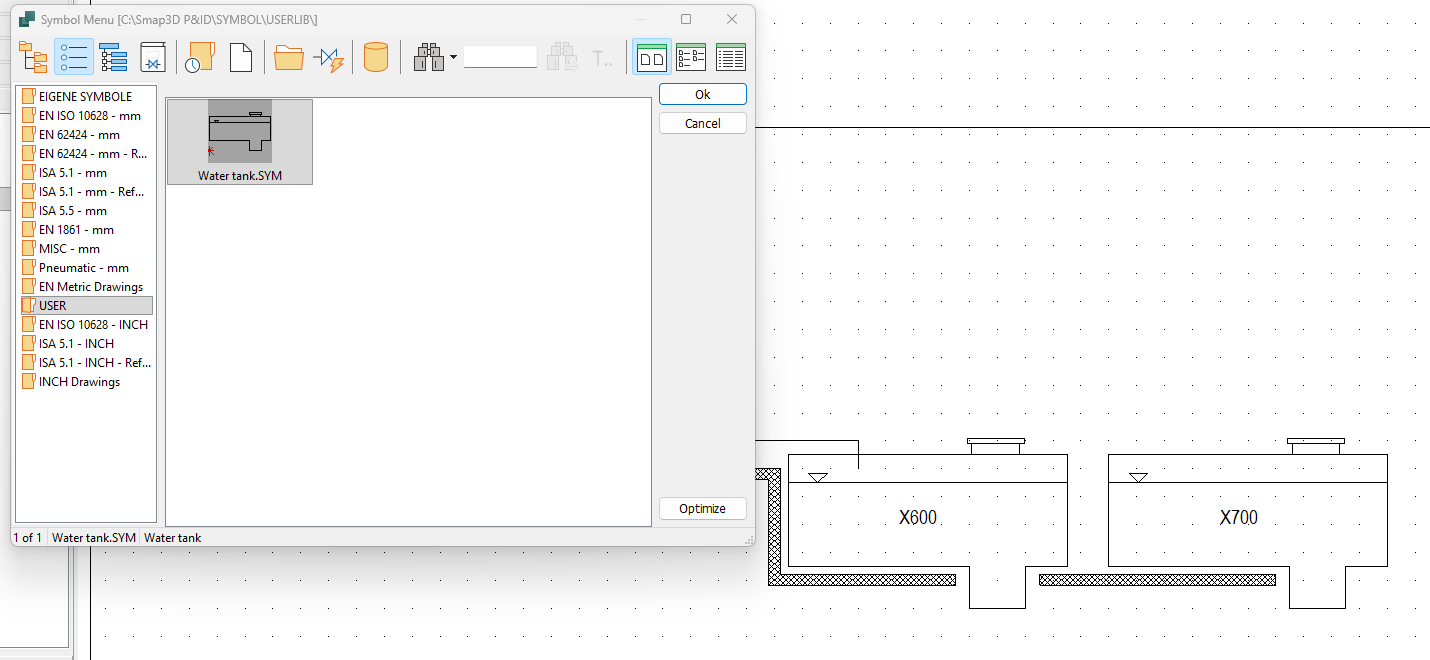
Figure 9 – Custom Symbol in the Library
CONNECTING THE P&ID TO THE 3D MODEL
Smap3D P&ID can be used as a standalone application.
However, companies using SolidWorks, Autodesk Inventor, or Solid Edge can connect the P&ID project directly to the 3D assembly.
The P&ID To-Do List allows the 3D designer to see which components and pipelines from the P&ID have already been placed in the 3D model and which items are still missing.
This creates a clearer connection between process design and physical plant layout.
Component and process information can also be transferred from the P&ID into the 3D model and then passed through to the piping isometric drawings.
This supports a continuous information flow across several engineering stages:
P&ID → 3D piping model → piping isometrics → manufacturing documentation
Instead of treating these documents as isolated outputs, Smap3D helps connect them as part of one consistent engineering workflow.
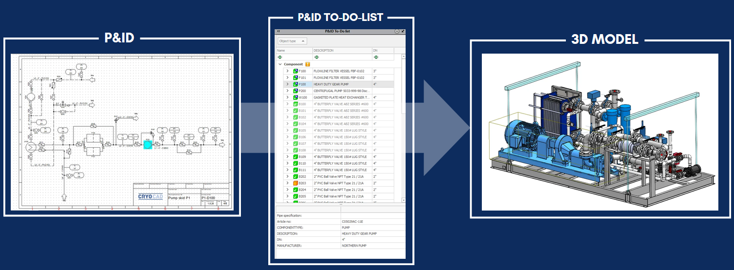
Figure 10 – P&ID To-Do List
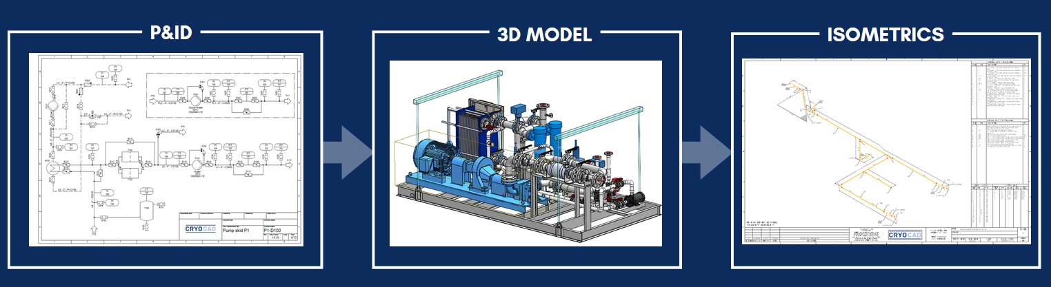
Figure 11 – Connected Engineering Workflow
A MORE CONNECTED ENGINEERING WORKFLOW
The features described here only represent a selection of what Smap3D P&ID can provide.
The main value of the software is not limited to faster drawing creation. Its real strength lies in combining graphical P&ID design with structured engineering data.
This can help companies:
- Reduce repetitive manual work
- Avoid inconsistencies between drawings and lists
- Improve component identification
- Reuse standardized design content
- Connect article data with engineering workflows
- Improve coordination between departments
- Transfer information from the P&ID into 3D plant design
- Maintain more consistent documentation through to manufacturing
For companies that already use SolidWorks, Inventor, or Solid Edge, the connection between the P&ID and the 3D model can be particularly valuable.
WATCH THE FULL OVERVIEW
To see these features in action, watch the full video walkthrough:
LEARN MORE ABOUT SMAP3D
CRYOCAD supports companies with Smap3D P&ID, Smap3D Piping, piping isometrics, implementation, database configuration, component preparation, training, and workflow optimization.
For further information or to discuss a specific Smap3D requirement, contact us.