SpaceDreams is a French-based spaceport architect developing modular and interoperable ground infrastructure for the emerging space economy. Their approach focuses on flexible, container-based systems that enable efficient launch operations across different locations and missions.
CRYOCAD was engaged to support the detailed engineering of fluidic lines connecting multiple process skids to the launcher interface. The scope covered the routing and integration of cryogenic and non-cryogenic piping between containerized systems (LOX, Helium, Nitrogen) and the launcher table structure. The project was executed as part of our modular skid design and process piping engineering services.
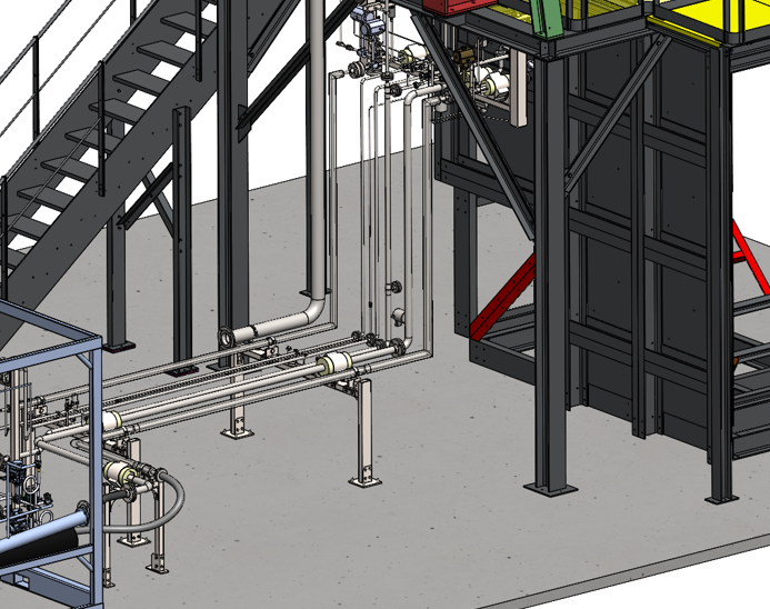
Figure 1 – Launcher Fluidic Lines
PROJECT SCOPE AND ENGINEERING CONTEXT
Our engineering scope focused on the interconnection between process skids (“Boxes”) and the launcher table manifold, including:
- Cryogenic LOX transfer lines
- High-pressure helium systems (up to ~400 bar)
- Nitrogen and pneumatic supply systems
- Ventilation lines
All systems were designed in accordance with PED 2014/68/EU and EN 13480, including requirements for material selection, welding, inspection, and pressure testing.
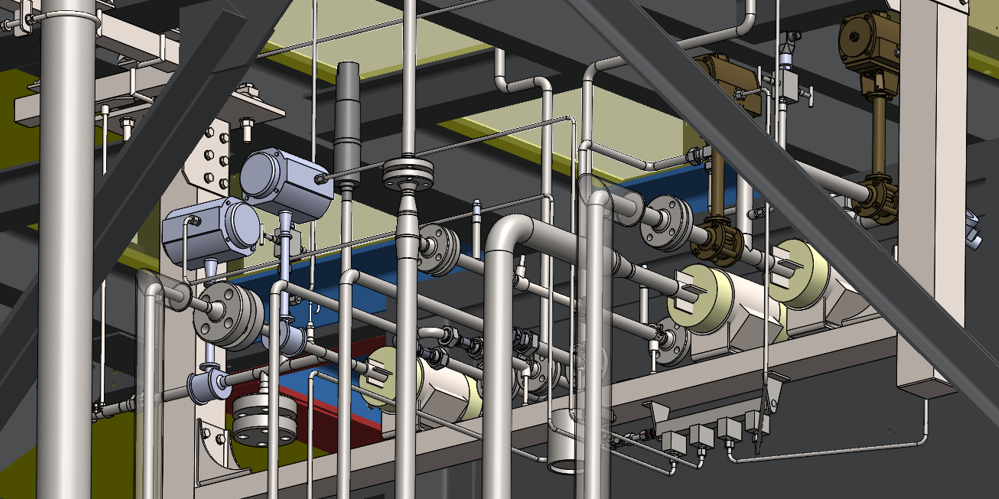
Figure 2 – Pipe Manifold Launcher Table
CRYOGENIC DESIGN: DOUBLE-WALL VACUUM-INSULATED PIPING
A key technical aspect of the project was the implementation of double-wall piping systems with vacuum insulation for cryogenic media such as LOX and helium.
This design significantly reduces heat ingress and prevents phase change or boil-off under operating conditions down to approximately −185 °C.
The engineering scope included the complete design of the vacuum-insulated system, covering routing as well as functional and safety-related components.
A critical safety feature was the integration of burst discs within the vacuum jacket, designed to protect the outer pipe in the event of an inner pipe rupture. This ensures controlled pressure relief and prevents structural failure of the insulation system.
DIGITAL ENGINEERING APPROACH WITH SMAP3D
CRYOCAD applied an integrated workflow using SolidWorks and Smap3D Plant Design.
Smap3D was selected due to:
- High flexibility in adapting routing during iterative design phases
- Specification-driven component management
- Automated generation of isometrics and spool drawings
- Reliable PCF export for downstream analysis
This approach enabled rapid adjustments, which is particularly important in cryogenic systems where routing may require refinement after stress validation.
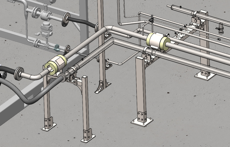
Figure 3 – Cryogenic Piping Design with SolidWorks & Smap3D
PIPE STRESS ANALYSIS AND ITERATIVE OPTIMIZATION
Pipe stress analysis was performed using ROHR2, based on PCF data exported from Smap3D.
The analysis included:
- Thermal contraction effects at cryogenic temperatures
- Internal pressure loads (up to ~400 bar)
- Structural constraints and boundary conditions
- Load transfer into supports and steel structures
This ensured that all systems remained within allowable stress limits and operational constraints.
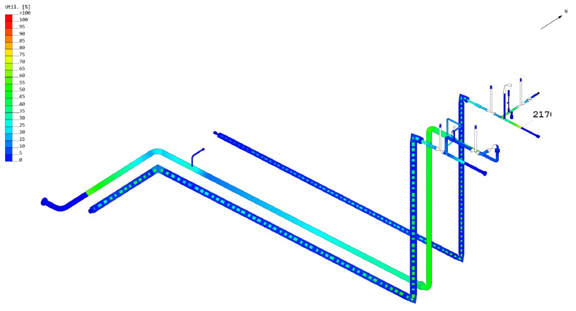
Figure 4 – Pipe Stress Analysis with ROHR2
PIPE SUPPORT ENGINEERING
Structural Supports (Hilti)
For secondary structures and support frames, CRYOCAD used the Hilti Construction Platform, enabling:
- Fast configuration of modular support systems
- Load verification based on stress analysis outputs
- Use of globally available, standardized components
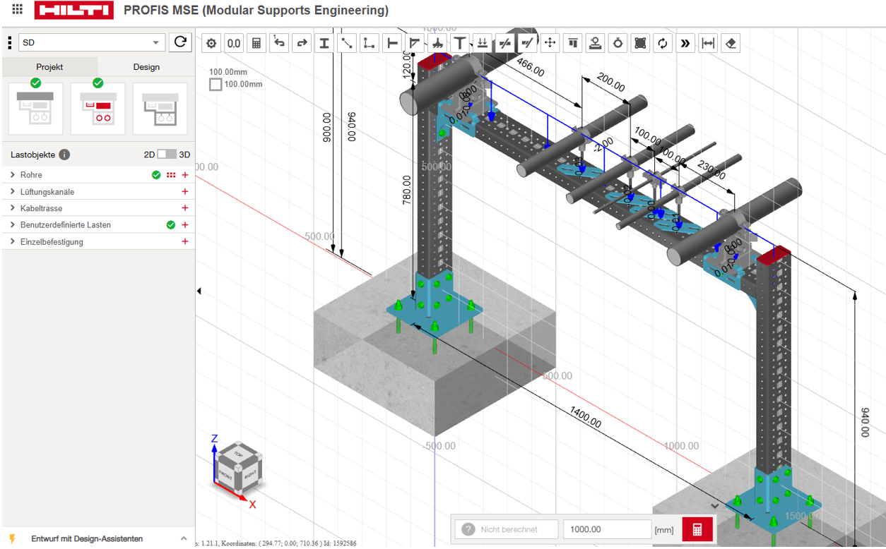
Figure 5 – HILTI MSE / Construction Platform
Cryogenic Line Supports (LISEGA)
For cryogenic piping, LISEGA supports were selected due to their suitability for:
- Low-temperature applications
- Controlled load transfer and guided movement
- Defined behavior under thermal contraction
These supports were integrated into the overall stress concept and positioned according to analytical results.
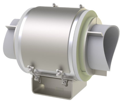
LISEGA Cryogenic Pipe Support — Source: lisega.de (April 2026)
FROM 3D MODEL TO FABRICATION
The final deliverables included a complete, fabrication-ready documentation package:
- 3D models and routing layouts
- Isometric drawings and spool definitions
- Bills of materials (BOM)
- General arrangement drawings
- Welding and testing specifications
The design ensured full compliance with applicable standards while also focusing on practical manufacturability and installation efficiency.
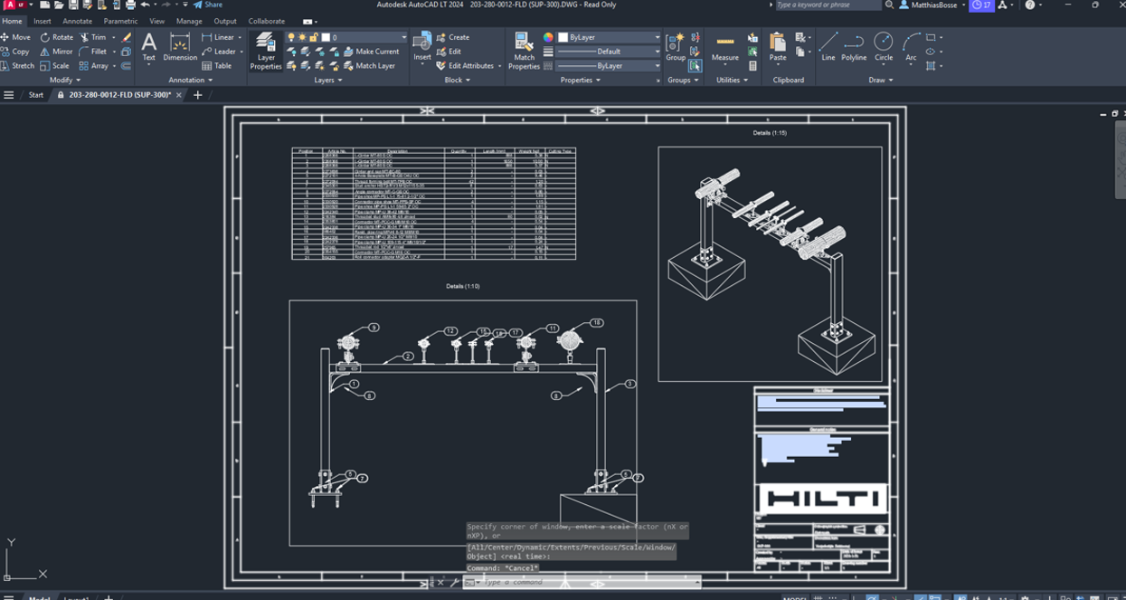
Figure 6 – HILTI MSE Drawing Export
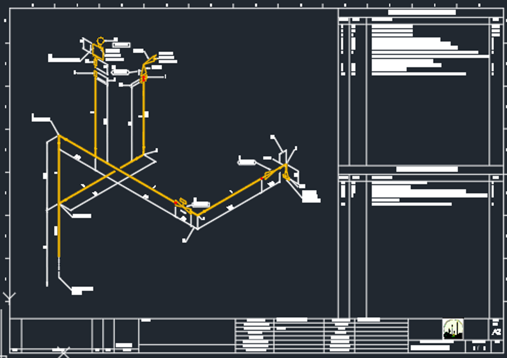
Figure 7 – Smap3D Isometric Drawing / PCF Export
CONCLUSION
This project demonstrates how complex cryogenic and utility piping systems can be engineered efficiently through a fully integrated workflow.
By combining:
- Advanced 3D design (SolidWorks / Smap3D)
- Direct integration with pipe stress analysis (ROHR2)
- Specialized cryogenic design (double-wall vacuum systems)
- Standardized and validated support solutions (LISEGA and Hilti)
CRYOCAD delivered a solution that is both technically robust and ready for real-world implementation.