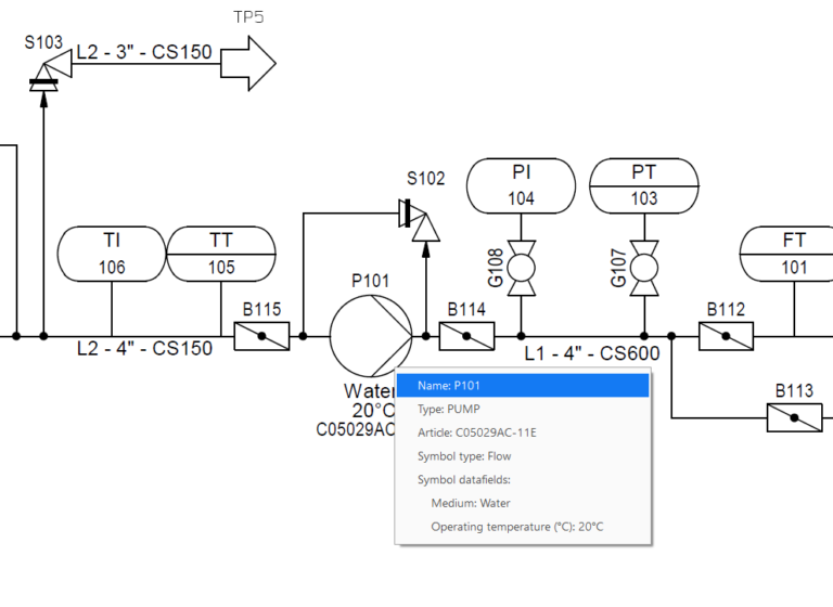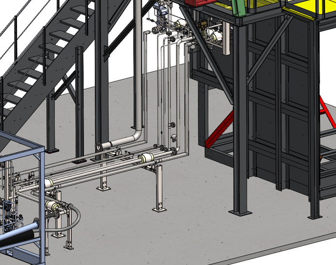
In many engineering and equipment manufacturing companies, the piping design process is still surprisingly manual.
- P&IDs are drawn with no real connection to the 3D model
- BOMs are created in Excel
- Isometrics are generated one by one.
- Modifications involve redoing complete documentation
This approach is not only time consuming. It also introduces errors, inconsistencies and risks in manufacturing.
This article shows how this flow can be completely transformed by automation, connecting P&ID, 3D model and isometric generation into a single coherent process.
The problem: disconnected processes
In a traditional flow:
- The P&ID is a static document
- The 3D model is built manually by interpreting the schematic diagram.
- Isometrics are created independently
- No real traceability between documents
Each change involves:
- Review multiple documents
- Manually maintain BOMs
- High risk of inconsistencies
This translates into:
- Hours (or days) of repetitive work
- Dependence on key people
- Manufacturing problems
The solution: an integrated flow with Smap3D
The approach shown in the video is based on a key principle:
A single data source for the entire design process
Smap3D allows you to connect:
- Intelligent P&ID
- 3D modeling of piping
- Automatic isometric generation
1. Smart P&ID as the basis for the project
Instead of being a simple drawing, the P&ID becomes a structured database.
Each component contains:
- Technical properties
- Unique identifiers
- Line information (pipeline)
This allows the P&ID to move from being an isolated document to being the starting point of the design.
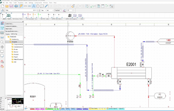
Figure 1 – P&ID in Smap3D
2. Direct transfer to the 3D model
From the P&ID, the lines and components are transferred to the 3D environment.
This involves:
- Automatic creation of pipelines
- Assignment of pipe specifications
- Total consistency between schematic and model
The designer no longer starts from scratch. He works on a structured basis, drastically reducing interpretation errors.
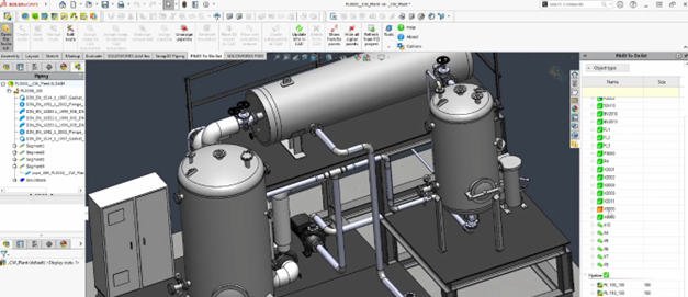
Figure 2 – Piping design in Smap3D
3. Specification driven 3D modeling
In the 3D environment:
- Components are inserted from specifications (pipe specs)
- No manual selection of parts one by one
- The system ensures automatic compatibility
This eliminates one of the biggest sources of error in piping design: incorrect component selection.
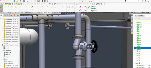
Figure 3 – Checklist in Smap3D
4. Automatic isometric generation
Once the 3D model is finished:
- Isometrics are generated automatically
- Dimensions, bills of materials and labels are included
- They can be generated per line or per spool
Without redrawing. No reinterpretation. Without duplicating work.
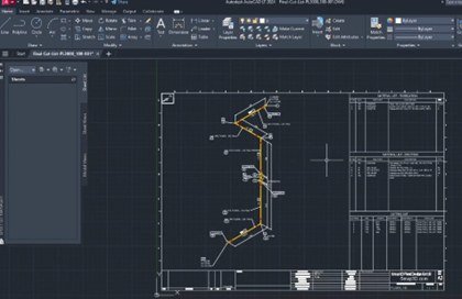
Figure 4 – Isometrics in Smap3D
5. Real impact on projects
This approach completely changes the way of working:
Time savings
- Significant reduction of repetitive tasks
- Elimination of manual work in documentation
Consistency
- All documents come from the same model
- Divergence between P&ID, 3D and isometric is avoided.
Traceability
- Each component maintains its information throughout the process.
- Controlled and automatically propagated changes
Preparation for production
- Isometrics ready for production
- Complete information without the need for reprocessing
Conclusion
Piping design should not rely on fragmented manual processes. Integration between P&ID, 3D and documentation is not just an incremental improvement. It is a structural change in the way we design.
Companies that adopt this approach don’t just work faster. They work with greater control, lower risk and better manufacturing quality.
To see the complete workflow in action, click on the video:
Do you want to apply this approach in your company?
If currently:
- Generate isometrics manually
- You maintain bills of materials in Excel
- You waste time on revisions and corrections
It’s time to rethink the process. An analysis of your current flow can quickly identify opportunities for automation.
If you want to evaluate how to apply this approach in your company, contact us. We will be happy to help you.